1 / 5

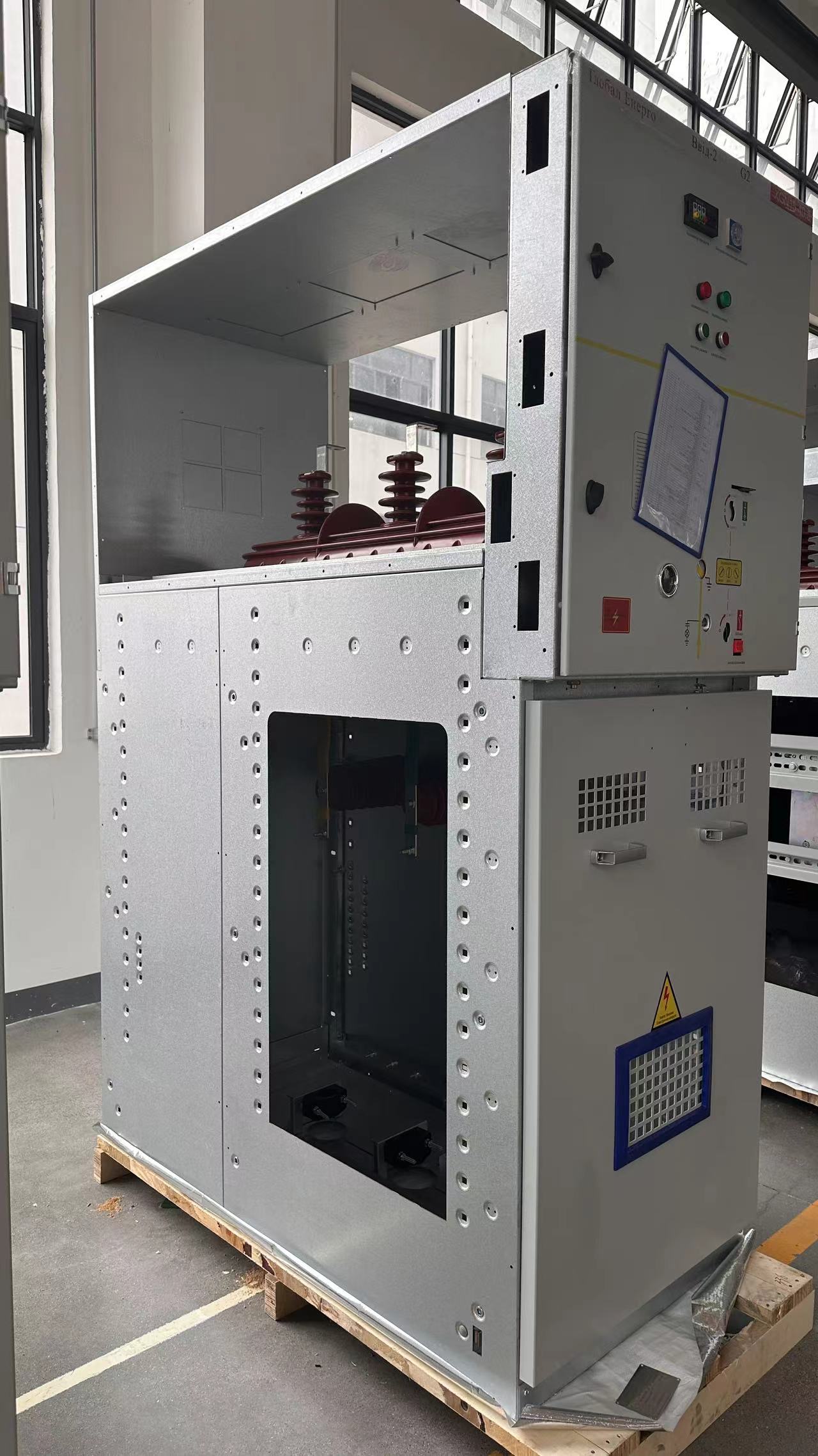
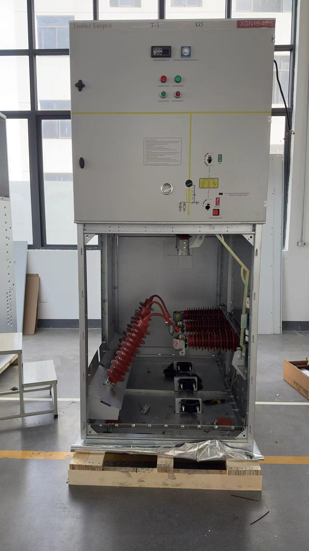
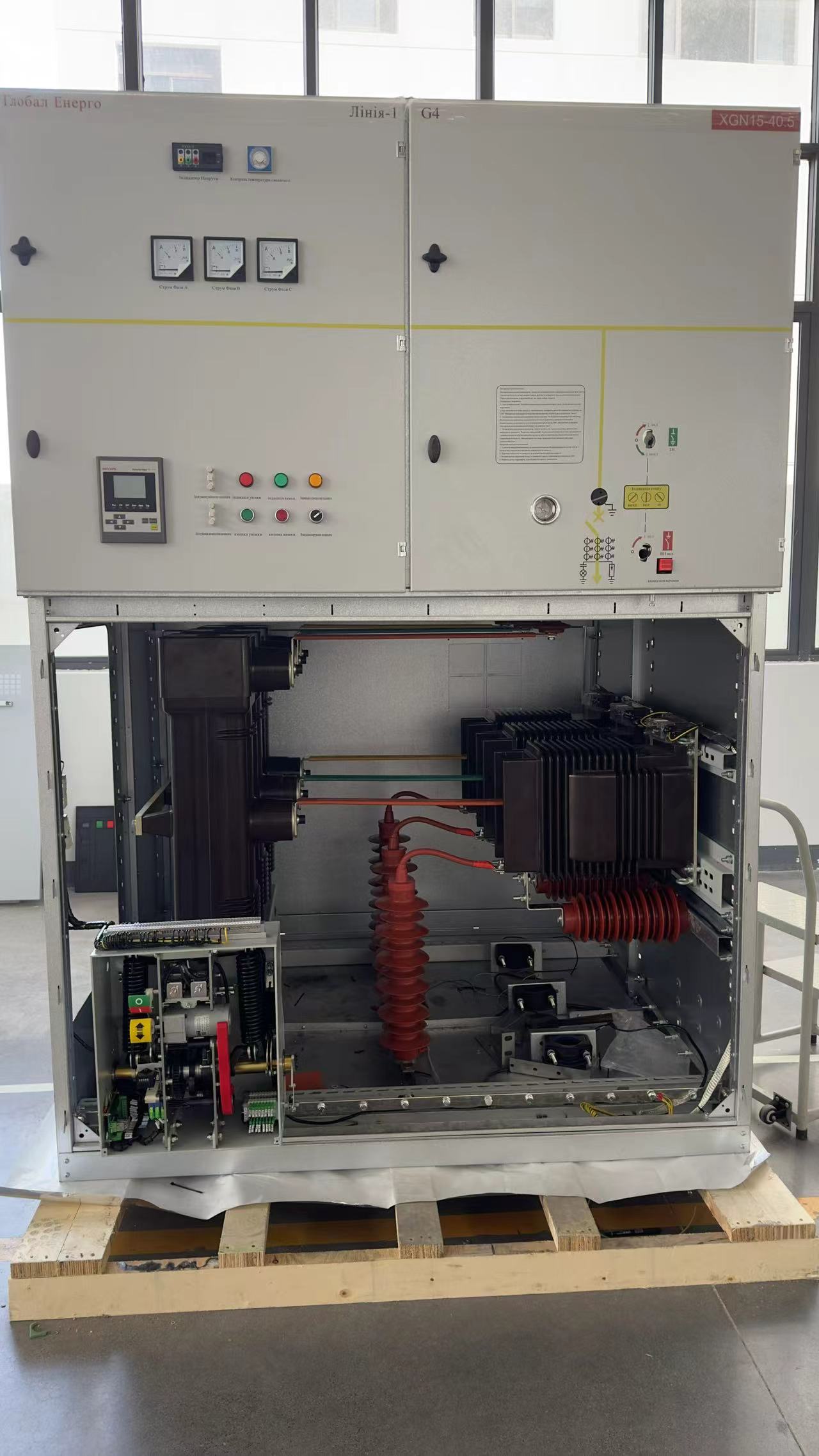
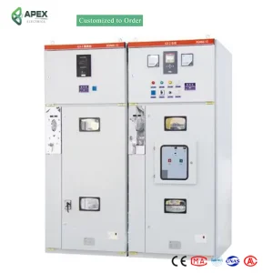
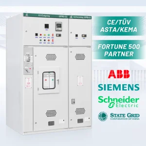
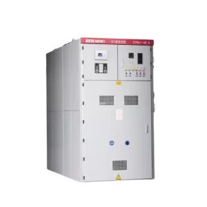
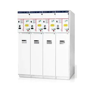
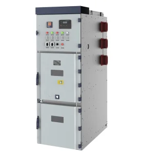
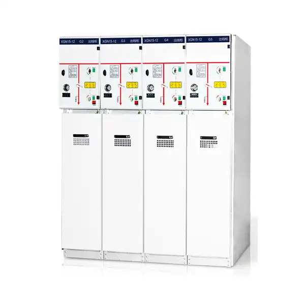
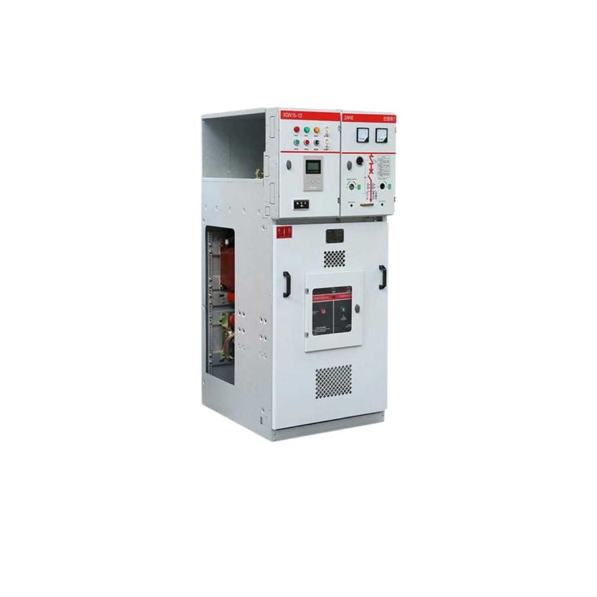
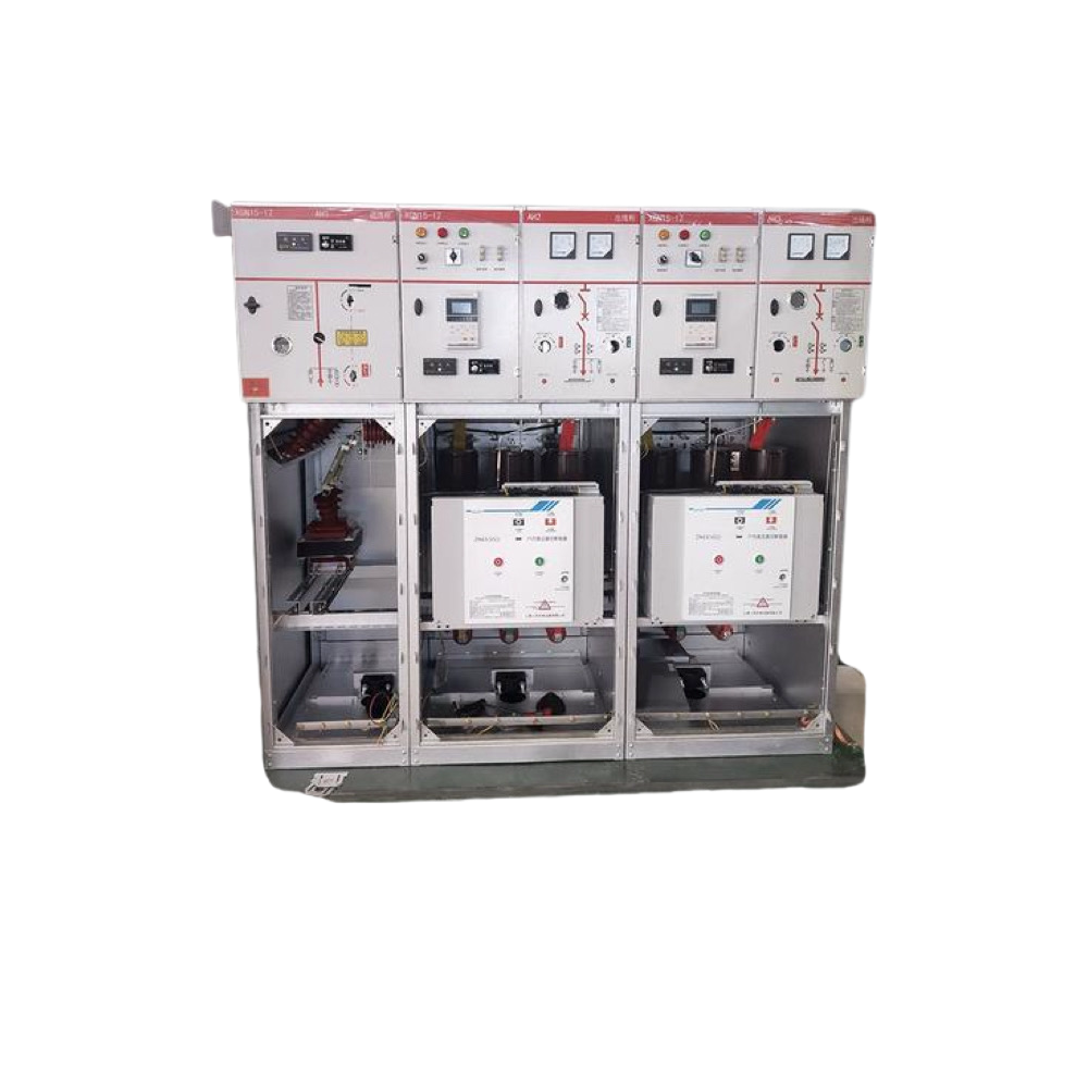
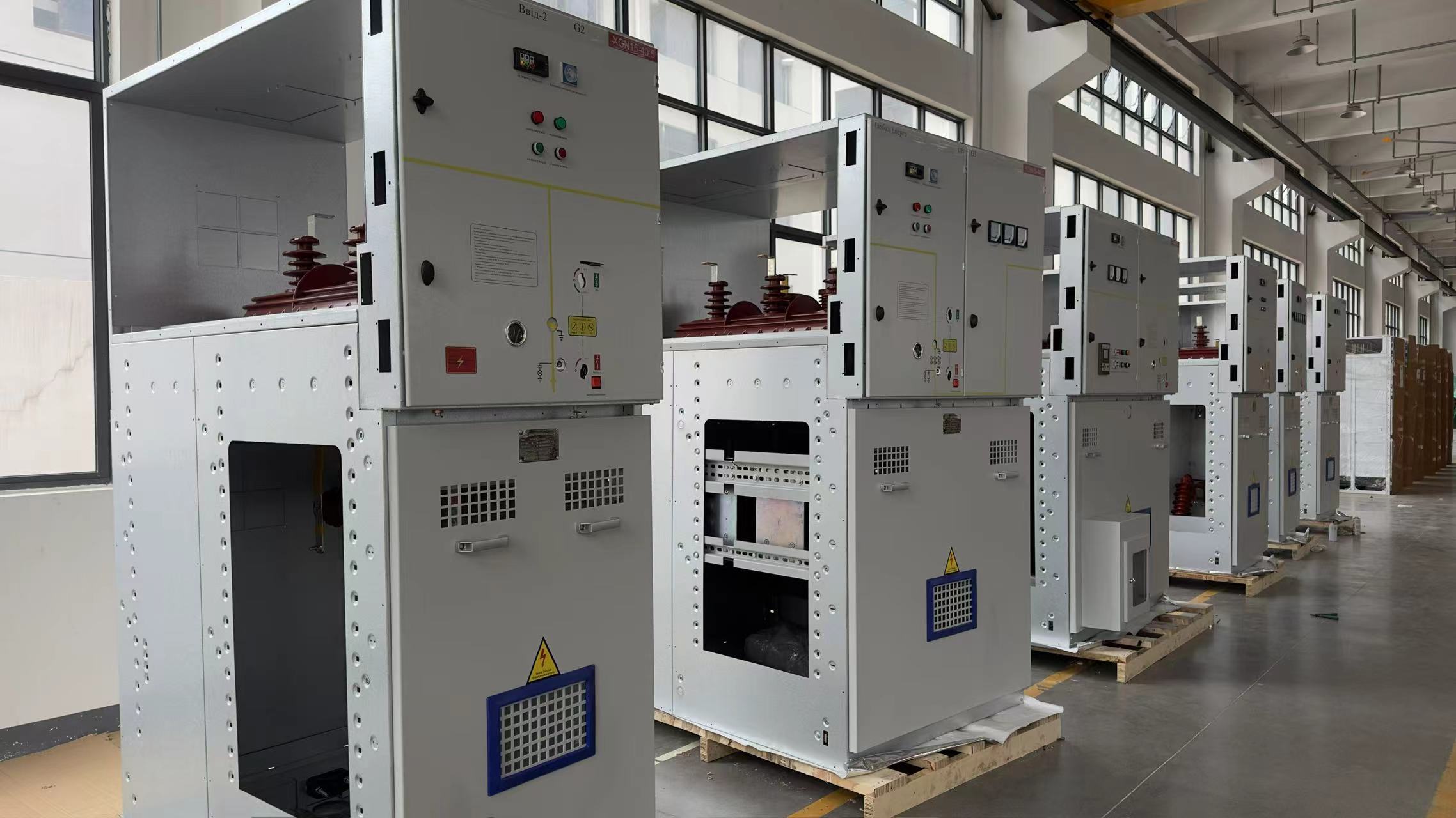
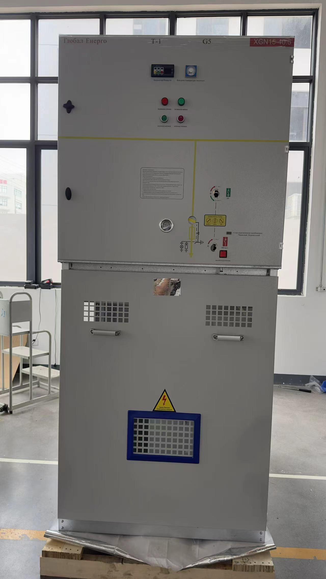
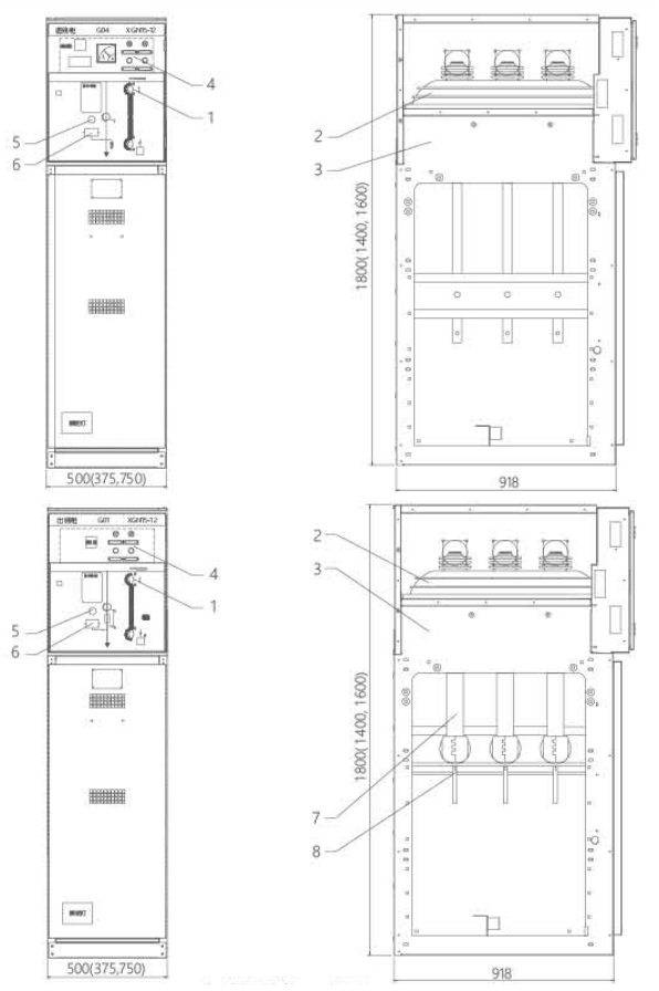
The bus room is arranged in the upper part of the cabinet body, and the main bus bars are connected together in the bus room and run through the whole row of switch cabinets. The busbar is arranged horizontally for easy expansion.
The load switch room is equipped with a load switch, the shell of the load switch is made of epoxy resin, filled with SF6 gas as arc extinguishing and insulating medium, and two transparent hot-pressed plastic end covers are arranged at the leading end of the operating shaft, through which the contact state can be observed. SF6 gas density meters or gas density meters with alarm contacts can be installed in the switch room according to customer requirements.
The circuit breaker room is located in the middle of the cabinet, which can be equipped with a special vacuum circuit breaker or SF6 circuit breaker according to customer needs, and its breaking capacity can meet the operation of normal switching and branch network, as well as breaking short-circuit current under special circumstances, etc., vacuum circuit breaker is especially suitable for frequent operation of network systems. The circuit breaker is equipped with a spring operating mechanism, which has the function of reclosing, and the action is reliable and the service life is long.
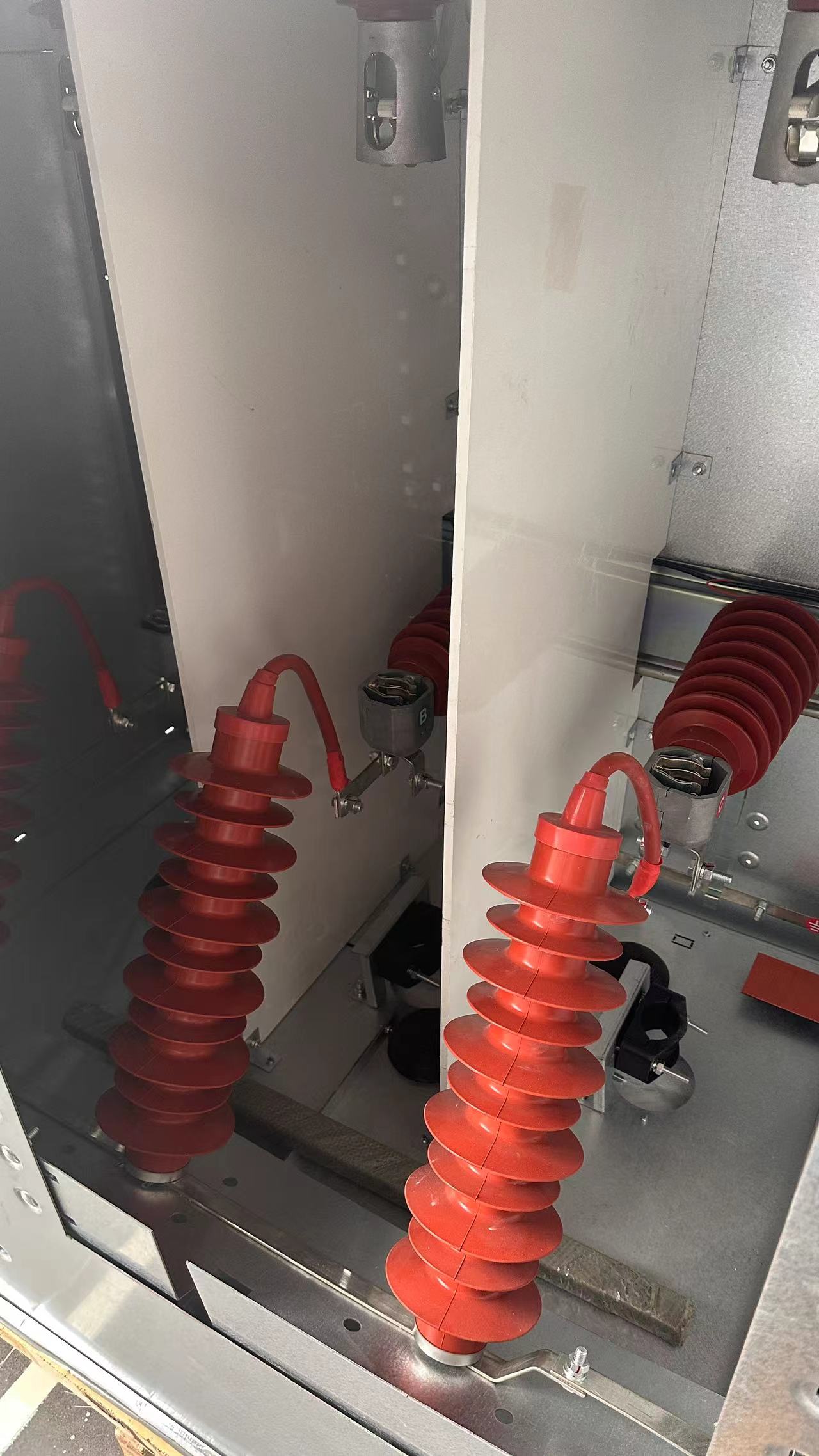
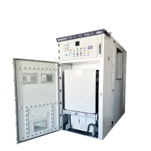
The cable room is mainly used for the connection of cables, so that the single-core or three-core cables can be connected with the simplest unshielded cable heads, and at the same time, the ample space can also accommodate components such as arresters, current transformers, and lower grounding switches. The cabinet door is designed as standard with viewing windows and safety interlocks, and the cable compartment floor is equipped with a sealing cover and a cable clamp of appropriate size with brackets. The front door frame of the cable room floor can be removed to facilitate cable installation.
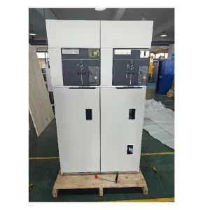
The interlocking low-pressure chamber also functions as a control screen. The low-voltage chamber is equipped with a spring-operated mechanism and a mechanical interlocking device with a position indicator, and can also be equipped with auxiliary contacts, trip coils, emergency tripping mechanisms, capacitive live display devices, key locks and electric operating devices, while the low-voltage chamber space can also be used for the installation of control loops, recording instruments and protective relays, and the 750mm wide cabinet is equipped with two identical low-voltage chambers, which can be equipped with more accessories.
| Number | Name | Unit | Value |
|---|---|---|---|
| 1 | Rated voltage | kV | 12 |
| 2 | Rated frequency | Hz | 50 |
| 3 | Main bus rated current/fuse maximum rated current | A | 630, 125 |
| 4 | The main circuit and ground circuit are rated for short-time withstand current | kA/S | 203 |
| 5 | The main circuit and ground circuit are rated for peak withstand current | kA | 50 |
| 6 | The main circuit and ground circuit are rated for short-circuit closing current | kA | 50 |
| 7 | The number of load switches interrupted at full capacity | time | 100 |
| 8 | Fuse interrupting current | kA | 31.5, 40 |
| 9 | Rated closed-loop interrupting current | A | 630 |
| 10 | Rated transfer current | A | 1600 |
| 11 | Mechanical life | time | 2000 |
| 12 | 1min power frequency withstand voltage (peak) interphase and ground/isolation fracture | kV | 4, 248 |
| 13 | Withstand voltage (peak) and ground/isolation fractures for lightning impulses | kV | 7, 585 |
| 14 | The secondary circuit has a power frequency withstand voltage of 1min | kV | 2 |
| 15 | Ingress protection | - | IP3X |