Wind turbines depend on step-up transformers to raise generator voltage for reliable grid delivery. When this equipment fails, production can stop immediately, even if the blades and generator remain healthy. The question “why do wind turbine step-up transformers fail” therefore deserves more than a simple maintenance answer. It involves insulation, heat, moisture, vibration, grid disturbances, and installation quality.
The U.S. Department of Energy’s Land-Based Wind Market Report shows continued growth in turbine size, with modern machines transferring greater electrical power through compact equipment. Higher loading leaves less tolerance for cooling problems and poor connections. NREL reliability studies also identify electrical components as important contributors to wind plant downtime, although failure records vary between sites. Field evidence is messy. A transformer may fail after years of normal operation, or after one severe event.
Typical warning signs appear inside the transformer tank. Darkened oil can indicate overheating. Moisture can weaken paper insulation. Partial discharge may damage bushings slowly. Loose terminations create hot spots that thermal cameras can reveal before a trip occurs. Harmonic currents from power electronics may increase additional heating. Lightning and switching surges can also puncture insulation without leaving obvious external damage.
IEC 60076 and IEEE transformer guidance emphasize correct design, testing, protection, and commissioning. DNV and DOE reports further show why wind assets require disciplined condition monitoring as turbines become larger and more remote. Operators should compare oil analysis, dissolved-gas trends, load history, relay records, and weather exposure. One overlooked detail can matter. A technically sound transformer can still fail because transport damage, inadequate grounding, or delayed inspection was underestimated. Better analysis begins by treating every failure as evidence, not merely as bad luck.
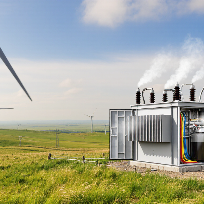
A wind turbine step-up transformer raises generator voltage before electricity enters the collection network. A typical turbine generator may produce about 690 volts, while the internal collection system commonly operates near 33 kilovolts. Higher voltage means lower current for the same power, reducing cable losses and heat. The transformer uses electromagnetic induction, insulated windings, bushings, cooling equipment, and sometimes an on-load tap changer to control voltage. It works quietly. That matters.
IRENA’s Renewable Capacity Statistics 2024 recorded more than 1,017 GW of global wind capacity by the end of 2023. The Global Wind Energy Council also reported approximately 117 GW of new wind installations that year. Each added turbine increases the importance of dependable voltage conversion.
The simple diagram hides the difficult part. Field inspections often find damage after repeated temperature changes, moisture entry, loose connections, or excessive electrical stress. A transformer can heat rapidly during high winds, then cool during low production. This repeated cycling weakens insulation and seals. Harmonics from power electronics may increase additional losses, although the impact depends on system design. Lightning and switching surges can also attack bushings and winding insulation. IEC 60076 provides the main technical framework for power-transformer design, testing, and operation, but compliance does not remove every site risk. Engineers still need oil or dry-type insulation checks, thermal scans, dissolved-gas analysis where applicable, and careful load records. Some failures begin as a faint odor, a small temperature imbalance, or an unusual sound. Maintenance teams may overlook these clues. That remains a practical weakness.
Why Do Wind Turbine Step-Up Transformers Fail?
How Operating Conditions Create Transformer Stress
Wind turbine step-up transformers rarely fail because of one dramatic event. Often, stress accumulates quietly during changing operating conditions. Rapid wind shifts make generator output rise and fall. Those cycles heat the windings, then cool them again. Repeated expansion can loosen clamping pressure and weaken insulation. Moisture makes the problem worse. A cold morning can draw humid air through imperfect seals. Later, internal heat turns that moisture into a serious insulation risk.
High wind creates another strain. The transformer may run near its rated load for hours, while poor ventilation keeps hot spots elevated. Harmonic currents from power electronics can add extra heating, even when measured load looks acceptable. Grid faults also produce mechanical forces inside the windings. Protection settings must respond quickly, but settings are not always reviewed after site changes. That gap deserves attention. In real inspections, oil temperature trends, dissolved-gas results, bushing condition, and cooling-fan performance provide stronger evidence than a single alarm. Still, diagnosis is not perfect. One abnormal reading can mislead a team if weather and loading history are ignored.
Tips
Record temperature, load, and wind speed together. Inspect breathers, seals, radiators, and cable terminations during planned outages. Compare vibration and oil data over time, not as isolated numbers. Check alarms after relay or network changes. Leave room for doubt. Small trends often reveal stress before smoke appears.
| Operating Condition | Typical Field Exposure | Primary Transformer Stress | Likely Failure Mechanism | Early Warning Indicators | Relative Risk | Recommended Control Measures |
|---|---|---|---|---|---|---|
| Frequent Load Cycling | Multiple daily starts, stops, and rapid power changes | Repeated thermal expansion and contraction of windings, clamping structures, and connections | Insulation fatigue, loosened connections, winding deformation, and accelerated aging of solid insulation | Increasing winding resistance imbalance, abnormal vibration, rising hot-spot temperature, and recurring protection alarms | High | Use thermal-cycle trending, inspect bolted connections, verify clamping integrity, and avoid unnecessary rapid switching |
| Sustained Overloading | Current above nameplate rating during high-wind periods or grid constraints | Excessive winding temperature and increased copper losses proportional to current squared | Thermal insulation degradation, loss of dielectric strength, premature oil oxidation, and winding hot-spot damage | High top-oil temperature, elevated calculated hot-spot temperature, activated overload alarms, and accelerated dissolved-gas trends | High | Coordinate turbine controls with transformer thermal limits, maintain cooling equipment, and apply loading limits based on ambient temperature |
| High Ambient Temperature | Hot-weather operation with limited natural heat rejection | Reduced thermal margin between operating temperature and insulation aging limits | Accelerated cellulose aging, oil deterioration, seal hardening, and reduced transformer life expectancy | Higher-than-normal top-oil temperature at the same load, frequent fan or pump operation, and decreasing cooling efficiency | Medium | Clean radiators, verify fan and pump performance, improve ventilation, and derate loading when required |
| Low Temperature and Moisture Ingress | Cold starts, condensation, rain, fog, or snow near outdoor equipment | Moisture lowers insulation resistance and creates thermal and mechanical stress during energization | Partial discharge, surface tracking, corrosion, and reduced dielectric withstand capability | Low insulation-resistance readings, increased moisture-in-oil results, breather saturation, and abnormal tan-delta values | Medium | Maintain sealed breathers, inspect gaskets and cable boxes, test insulation before energization, and control condensation |
| Grid Voltage Variation | Voltage deviations, tap changes, or operation near the upper voltage limit | Higher core flux and increased excitation current when volts-per-hertz rises | Core overheating, excessive magnetizing current, localized insulation stress, and nuisance protection trips | Increased no-load current, abnormal audible hum, elevated core temperature, and overexcitation relay operation | High | Monitor voltage and frequency together, verify tap-changer settings, and prevent operation outside the volts-per-hertz limit |
| Harmonic Distortion | Power-electronic converter switching and distorted grid current | Additional eddy-current and stray-flux losses in windings, clamps, tank, and structural parts | Localized overheating, vibration, acoustic noise, and insulation aging at hot spots not captured by average temperature | Elevated temperature with moderate RMS load, increased audible noise, waveform distortion, and abnormal infrared patterns | Medium | Measure voltage and current harmonic spectra, confirm transformer derating requirements, and address resonance or filtering issues |
| Converter and Switching Transients | Fast switching events, breaker operations, faults, and cable energization | High-frequency voltage distribution across winding insulation and steep transient overvoltages | Interturn insulation breakdown, partial discharge, bushing damage, and winding-to-ground faults | Transient recorder events, rising partial-discharge activity, abnormal surge-arrester leakage, and unexplained protection trips | High | Coordinate surge protection, verify cable and transformer insulation coordination, and analyze switching-event records |
| Lightning and External Surges | Direct or nearby lightning strikes on overhead lines, towers, or collection circuits | Short-duration dielectric stress across bushings, windings, and ground insulation | Turn-to-turn failure, bushing flashover, surge-arrester failure, and winding-to-ground breakdown | Arrester counter changes, leakage-current increase, damaged external insulation, and sudden gas or pressure alarms | High | Maintain grounding and bonding, inspect surge arresters, keep protective leads short, and review lightning protection zones |
| Poor Grounding or Ground-Fault Current | High ground impedance, damaged bonding, or repeated collection-system faults | Uneven voltage distribution and high electromagnetic forces during fault events | Tank potential rise, winding displacement, core insulation damage, and repeated bushing or cable stress | Ground-grid resistance changes, relay event records, unusual neutral current, and visible bonding corrosion | High | Test the grounding system periodically, verify neutral connections, and inspect fault-current paths after every major event |
| Mechanical Vibration and Transport Shock | Continuous turbine vibration, foundation movement, or improper handling during installation | Mechanical fatigue of bushings, leads, winding supports, and bolted joints | Loose connections, cracked support components, oil leaks, winding movement, and progressive insulation damage | Changes in vibration spectrum, loosened hardware, oil seepage, abnormal noise, and increased electrical imbalance | Medium | Use vibration trending, verify foundation and mounting torque, inspect after transport, and correct structural resonance |
| Cooling-System Degradation | Blocked radiators, failed fans or pumps, dirty heat exchangers, or control faults | Reduced heat transfer and rising internal temperature at normal electrical load | Overheating, insulation aging, oil sludge formation, and forced outage caused by thermal protection | Fan or pump alarms, increasing temperature differential, abnormal oil-flow readings, and repeated thermal trips | High | Function-test cooling stages, clean heat-transfer surfaces, inspect motors and controls, and maintain spare cooling components |
| Oil Contamination or Degradation | Moisture, oxygen exposure, particles, overheating, or inadequate oil maintenance | Reduced dielectric strength and impaired heat transfer through the insulating medium | Partial discharge, internal arcing, paper insulation aging, sludge formation, and restricted oil circulation | Low breakdown voltage, high water content, increased acidity, rising interfacial tension changes, and dissolved-gas abnormalities | High | Perform routine oil sampling, correct leaks, maintain breathers, filter or process oil when justified, and trend test results |
| Aging Seals and Bushings | Long service exposure to heat, ultraviolet radiation, vibration, and weather | Loss of sealing pressure and deterioration of external insulation surfaces | Oil leakage, moisture entry, bushing power-factor increase, flashover, and terminal connection failure | Visible cracks, oil seepage, discoloration, abnormal capacitance or dissipation-factor results, and surface tracking | Medium | Inspect seals and bushings visually and electrically, repair leaks promptly, and replace components before condition limits are exceeded |
| Note: Risk levels are general engineering guidance. Actual transformer stress depends on design, insulation system, loading profile, cooling class, grid characteristics, environmental exposure, maintenance quality, and protection settings. | ||||||
Wind turbine step-up transformers operate under changing loads, vibration, and harsh weather. These conditions expose weaknesses that routine inspections may miss.
Overheating is a common failure mode. Watch for rising oil temperatures, blocked radiators, or unusual fan operation. A sharp temperature increase during moderate wind deserves attention. Insulation damage may follow. Dissolved gas analysis can reveal overheating, arcing, or paper degradation before a major fault occurs. Results need trend analysis, not a single reading.
Moisture creates another serious risk. It lowers insulation strength and can enter through damaged seals, breathers, or condensation. Cloudy oil, declining insulation resistance, and frequent protection alarms are warning signs. Leaking bushings may show oil stains, cracked porcelain, or surface tracking. Listen for new humming, clicking, or vibration. These sounds are easy to dismiss in a busy wind farm.
Winding faults often develop after repeated thermal stress. Sudden relay trips, phase-current imbalance, or abnormal temperature differences may indicate internal damage. A failed cooling system can accelerate the process. Field teams sometimes replace a sensor without checking the underlying trend. That mistake is understandable, but costly. Confirm alarms with oil tests, infrared scans, electrical measurements, and a careful visual inspection. No single symptom proves failure. The pattern usually tells more.
Why Do Wind Turbine Step Up Transformers Fail?
Engineers diagnose transformer problems by combining evidence, not trusting one alarm. In field inspections, they begin with relay records, oil temperature, load history, and cooling-fan performance. A sudden trip may indicate an internal fault, but it may also reflect a faulty sensor or loose connection.
Dissolved gas analysis provides important clues. Hydrogen can suggest partial discharge, while acetylene may indicate arcing. Moisture testing, insulation resistance, winding resistance, and power-factor measurements reveal different weaknesses. Thermal imaging then checks bushings, cable joints, radiators, and cabinet terminals under load. CIGRE Technical Brochure 642 identifies insulation systems, bushings, and tap changers among recurring transformer failure areas. These findings support a layered diagnostic approach.
Wind turbines create difficult conditions. The U.S. Department of Energy’s Land-Based Wind Market Report: 2024 Edition records an average installed turbine capacity of about 3.4 MW in 2023. Larger machines impose higher electrical and thermal stress. Engineers must compare present readings with earlier trends, not isolated values. Salt, vibration, lightning, harmonics, and repeated load changes can slowly damage insulation. A clean oil sample does not prove the transformer is healthy. Our first hypothesis is sometimes wrong. The overlooked detail may be a discolored terminal, a blocked air path, or a five-minute temperature rise during peak wind.
Wind turbine step-up transformers often fail from heat, moisture, vibration, and electrical stress. Their workload is increasing. The U.S. Department of Energy’s 2023 Land-Based Wind Market Report recorded an average new turbine capacity of 3.4 MW in 2022. Larger generators push more current through compact transformer systems.
Preventive work should begin with temperature control. IEEE Std C57.91-2011 indicates that every 6°C rise in insulation temperature can roughly halve its expected life. Operators should trend winding temperature, oil temperature, load, and cooling-fan performance. A hot spot above normal limits deserves inspection, not just a reset. CIGRE Technical Brochure 642 identifies insulation deterioration, bushings, tap changers, and connections as recurring transformer concerns. Oil samples should be tested for dissolved gases, moisture, acidity, and particle contamination. Darkened oil is a warning sign.
Physical inspections also matter. Check cable lugs for looseness, examine bushings after storms, and inspect enclosure seals after heavy rain. Infrared scans can reveal a warm termination before it becomes a shutdown. Surge protection and careful grounding reduce lightning damage. Harmonic measurements are useful when converters operate near their limits. Small details matter.
Condition-based maintenance is stronger than a fixed calendar alone. Still, sensors can fail, and inspection records are sometimes incomplete. That weakness needs attention. Keep clean oil-handling equipment, calibrated instruments, and a tested emergency spare plan. These practices cost time, but they can prevent a transformer failure from stopping an entire turbine for weeks.
Stress often accumulates quietly. Rapid wind changes repeatedly heat and cool the windings. This expansion can loosen clamping pressure and weaken insulation.
Cold mornings may draw humid air through worn seals. Internal heat later turns moisture into an insulation risk. Small leaks matter.
Yes. Strong winds can keep the transformer near rated load for hours. Poor ventilation may raise internal hot-spot temperatures.
Harmonic currents can add heating, even when the measured load looks acceptable. A normal load reading is not complete proof of safety.
Engineers compare relay records, oil temperature, load history, and cooling-fan performance. They also inspect bushings, radiators, cable joints, and terminals.
Hydrogen may suggest partial discharge. Acetylene may indicate arcing. These results need context from moisture, loading, and temperature history.
One abnormal result can mislead a team. Weather, wind speed, and recent loading may explain the change. We can still miss something.
Record temperature, load, and wind speed together. Inspect breathers, seals, radiators, and cable terminations during outages. Compare oil and vibration data over time.
Yes. Relay or network changes may leave alarms poorly reviewed. Settings should be checked again after modifications, even when the turbine operates normally.
Wind turbine step-up transformers increase the generator’s voltage so electricity can be transmitted efficiently to the grid. However, demanding operating conditions can place continuous stress on their insulation, windings, core, and cooling systems. Temperature fluctuations, moisture, vibration, electrical surges, frequent load changes, and harmonics may gradually weaken internal components. Understanding why do wind turbine step-up transformers fail requires examining how these stresses develop over time and how they affect transformer performance.
Common failure modes include insulation breakdown, winding damage, overheating, oil deterioration, bushing problems, and core faults. Warning signs may include unusual noise, rising temperatures, gas formation, oil leaks, abnormal electrical readings, or repeated protective trips. Engineers diagnose problems through visual inspections, thermal monitoring, dissolved gas analysis, insulation testing, and electrical measurements. Preventive strategies include regular maintenance, proper cooling, moisture control, surge protection, condition monitoring, and timely replacement of degraded parts. With accurate diagnosis and a planned maintenance program, operators can reduce unexpected outages, improve reliability, and extend transformer service life.

Zeno Electric