A prefabricated power substation is built in a factory, transported to site, and connected to the local electrical network. Its compact enclosure can protect transformers, switchgear, cables, and control equipment from weather and dust. But factory construction does not make a substation maintenance-free. Heat, moisture, corrosion, heavy electrical loads, and poor ventilation can all shorten component life. Small clues matter.
A common planning question is “what is the lifespan of prefabricated power distribution substations”? There is no single reliable number for every installation. Service life depends on design quality, equipment ratings, operating conditions, installation practices, and the care given over time. The enclosure may remain sound while a transformer, battery, fan, or protective relay needs repair or replacement. Records help. So do routine inspections.
This guide explains practical ways to extend a substation’s useful life, from managing temperature and preventing water ingress to checking electrical connections and maintaining protection systems. It also considers inspection schedules, component replacement, and the warning signs that deserve prompt attention. A warm cabinet, unusual odor, loose cable termination, or rising humidity reading may seem minor, yet each can point to a developing problem. These checks cannot guarantee a specific lifespan, and site conditions vary more than a simple checklist suggests. Still, consistent maintenance and accurate service records help operators make informed decisions, reduce avoidable stress on equipment, and plan replacements before failures disrupt power.
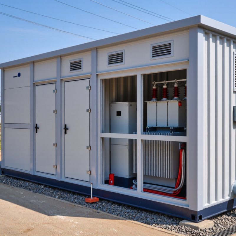
How to Extend Prefabricated Power Substation Lifespan
A prefabricated substation can serve reliably for decades, but its lifespan depends on daily operating conditions. Continuous overload creates heat inside the transformer and switchgear. Repeated heat cycles weaken insulation, seals, and cable terminations. Ambient temperature also matters. A poorly ventilated enclosure may trap heat on a sunny afternoon. Moisture is another serious factor. Condensation can corrode busbars, terminals, and protection devices, especially in coastal or dusty locations.
Maintenance quality often determines whether small defects become expensive failures. Technicians should inspect bolted connections, grounding conductors, door seals, and ventilation filters at scheduled intervals. Thermal imaging can reveal loose connections before they produce visible damage. Insulation resistance tests and protective relay checks should follow qualified procedures. Cleaning must be careful. Excessive pressure can force water into sensitive compartments. In my experience, maintenance records are sometimes incomplete, which makes fault patterns difficult to identify. That weakness deserves attention.
Tips: Keep loading within the designed range, and record peak temperatures during seasonal operation. Remove dust before it absorbs moisture. Check for unusual humming, burnt odors, cracked insulators, or oil leakage. Replace damaged gaskets promptly. A simple inspection log can show whether a temperature rise is occasional or becoming normal. Do not ignore minor corrosion. It rarely improves by itself. Also, review ventilation after nearby construction, because new walls or stored materials can restrict airflow. Testing intervals should reflect local climate, equipment age, and operating importance rather than follow a fixed calendar alone.
Environmental exposure, loading, thermal management, corrosion protection, and preventive maintenance are the main factors that determine the service life of a prefabricated power substation.
The chart presents typical engineering planning ranges rather than guaranteed values. Clean indoor installations can often achieve longer service lives, while coastal, humid, polluted, or poorly maintained installations may require earlier refurbishment. Regular inspections, moisture control, corrosion treatment, thermal monitoring, and keeping average loading below the equipment rating can significantly improve reliability.
How to Extend Prefabricated Power Substation Lifespan
Assessing a prefabricated substation starts with its actual condition, not its installation date. The U.S. Department of Energy reported that more than 70% of large power transformers were over 25 years old. Age matters, but heat, moisture, dust, and loading often accelerate deterioration. Record monthly temperatures, transformer loading, humidity, and alarm history. Compare these records with the equipment’s design limits.
Inspect the enclosure after storms and seasonal changes. Look for failed seals, blocked louvers, rust around cable entries, and standing water beneath the floor. Salt deposits near coastal sites deserve early attention. Infrared thermography can reveal loose connections and uneven heating while equipment remains energized. For oil-filled transformers, dissolved gas analysis should follow IEC 60599 guidance. IEEE C57.104 also supports gas interpretation for developing insulation faults. A clean enclosure can still hide a tired bushing.
Switchgear needs equal attention. Check insulation resistance, contact wear, operating time, and partial-discharge evidence according to qualified maintenance procedures. NETA’s maintenance guidance emphasizes condition-based testing rather than relying only on fixed intervals. That principle is practical, though not perfect. Test results can vary with temperature, instruments, and technician skill. Keep original readings, photographs, and corrective actions in one traceable record. No single score is enough. A substation beside a busy road may need more frequent cleaning than one in a dry rural area, even with identical equipment.
Use this sample assessment as a practical inspection guide. The example findings are illustrative; acceptance limits and maintenance intervals should follow the equipment manufacturer’s instructions, applicable electrical codes, and site-specific risk assessment.
| Assessment Area | Condition Indicator | Assessment Method | Illustrative Finding | Interpretation | Recommended Action | Priority |
|---|---|---|---|---|---|---|
| Enclosure and weather protection | Water ingress, damaged seals, blocked drains, or corrosion | Visual inspection of doors, roof joints, cable entries, ventilation openings, and drainage paths | Water staining below one cable-entry gland; door seal is compressed but intact | Ingress can accelerate corrosion, damage insulation, and reduce service life | Inspect and reseal the cable entry with compatible materials; verify enclosure protection after repair | High |
| Ambient temperature and ventilation | Room or enclosure temperature, airflow, and ventilation-fan condition | Record temperature during representative loading; check fan operation, filters, louvers, and airflow | Ambient temperature is 34°C; one ventilation filter is heavily dust-loaded | Elevated temperature and restricted airflow can accelerate insulation and component aging | Clean or replace the filter, confirm fan operation, and review ventilation capacity against equipment requirements | Medium |
| Transformer thermal condition | Winding or oil temperature, cooling performance, and temperature trend | Review temperature indicators and alarms; compare readings with load and manufacturer limits | Oil temperature is 78°C at 82% load, with no active temperature alarm | A single reading is not conclusive; loading, ambient temperature, cooling design, and historical trends matter | Record readings under comparable conditions and investigate any persistent upward trend or alarm | Medium |
| Electrical connections | Loose, oxidized, or overheating joints and terminations | Thermal imaging under stable operating load; compare similar phases and verify suspect points safely | One low-voltage termination is 18°C warmer than comparable phase connections | A phase-to-phase temperature difference may indicate a high-resistance connection or uneven loading | Plan a safe outage, inspect and repair the connection, then repeat the thermal survey under similar load | High |
| Insulation condition | Insulation resistance, leakage, tracking, or visible cracking | Inspect for contamination and damage; perform insulation tests using approved procedures and compare with baseline results | Insulation resistance is lower than the previous annual result; test temperature and setup were not identical | Test results depend on temperature, humidity, equipment configuration, and test method; trends are more useful than an isolated value | Repeat the test under documented, comparable conditions and investigate a confirmed declining trend | High |
| Moisture and condensation | Relative humidity, condensation, heater operation, and moisture indicators | Check enclosure humidity, anti-condensation heaters, and signs of moisture on internal surfaces | Relative humidity reaches 82% overnight; a cabinet heater is not operating | Repeated condensation can cause corrosion, tracking, and insulation deterioration | Repair the heater or humidity-control system, remove moisture safely, and check affected insulation and terminals | High |
| Corrosion and pollution | Rust, coating damage, salt deposits, dust, or chemical contamination | Inspect enclosure surfaces, structural supports, busbar compartments, and exposed fittings | Light surface corrosion is present on external fasteners near a coastal-facing wall | Salt-laden or industrial atmospheres can increase corrosion rates and impair electrical clearances | Remove corrosion using an approved method, restore protective coating, and increase inspection frequency for exposed areas | Medium |
| Grounding and bonding | Bonding integrity, earth connections, and grounding-system test results | Inspect conductors and joints; test using the approved site procedure and compare with design criteria and prior results | Grounding conductor is intact; measured earth resistance is 3.2 Ω, compared with 2.7 Ω at the previous test | Acceptability depends on system design and local requirements; a changing result warrants review | Check test conditions and connections, investigate the trend, and verify compliance with the site grounding design | Medium |
| Protective devices and controls | Relay alarms, trip-circuit health, breaker operation, and control-power condition | Review event logs and settings; test functions according to the maintenance program and approved procedures | No active alarms; the trip-circuit supervision indication is intermittent | An intermittent indication may point to a control-circuit, wiring, or auxiliary-contact issue | Investigate the trip circuit and verify correct operation before the next planned maintenance interval | High |
| Foundation and external environment | Settlement, vibration, standing water, vegetation, and access clearance | Inspect the plinth, cable trenches, drainage, surrounding ground, and equipment clearances | Minor soil erosion is visible beside one corner of the foundation; no visible enclosure distortion | Ongoing erosion or settlement can stress cable connections and affect enclosure alignment | Restore drainage and ground support; document reference points and monitor for further movement | Medium |
| Load and operating history | Peak loading, load imbalance, switching events, faults, and alarm trends | Review metering data, protection records, maintenance history, and operating logs | Peak loading reached 96% of the rated value for two hours on several summer days | Repeated high loading can raise operating temperature and reduce the margin for abnormal conditions | Review load growth and phase balance; assess cooling performance and capacity planning with a qualified engineer | Medium |
Moisture is often the enclosure’s quietest threat. Condensation forms when a cold metal wall meets warm, humid air. Use sloped roofs, sealed cable entries, and breathable pressure vents. These details reduce trapped water without creating permanent openings.
Keep it dry. Small gaps matter.
Inspect door gaskets, hinges, roof joints, and cable glands every six months. Look for powdery rust, peeling coatings, and water marks near the floor. IEC 60529 enclosure testing supports selecting suitable ingress protection for local conditions. However, an IP rating is not a maintenance plan.
In coastal or polluted areas, wash deposited salts with approved methods, then dry the surfaces completely. I have seen corrosion begin behind an apparently intact gasket.
Heat accelerates electrical aging and weakens protective coatings. IEC 62271-1 identifies 40°C as the maximum normal ambient temperature for many high-voltage assemblies. IEEE C57.91 applies a practical transformer rule: insulation aging can roughly double for each 6°C rise above a reference hot-spot temperature.
Provide clear airflow paths, shade the enclosure, and keep ventilation filters clean. Avoid placing exhaust outlets beside intake openings. This mistake is common.
NACE’s IMPACT study estimated global corrosion costs at about 3.4% of global GDP, or US$2.5 trillion annually. That figure supports disciplined coating inspections, but it cannot replace site-specific judgment.
Record humidity, surface temperature, and repair dates; imperfect records still reveal recurring trouble.
A prefabricated power substation can serve for decades, but only with disciplined inspection. The U.S. Department of Energy reports that distribution transformers commonly have a service life of 25 to 40 years. Heat, moisture, vibration, and loose connections can shorten that range. Inspectors should record enclosure temperature, corrosion, cable lug torque, grounding continuity, and unusual noise during every scheduled visit. Small signs matter.
Electrical testing should include insulation resistance, contact resistance, breaker timing, and protective relay verification. Infrared scans can reveal hot terminals before visible damage appears. NFPA 70B now treats electrical maintenance as a formal safety requirement, not an optional recommendation. Maintenance records should include test values, instrument details, weather conditions, and corrective actions. Missing context weakens the record.
Mechanical components need equal attention. Check door seals, hinges, lifting points, ventilation filters, fan bearings, busbar supports, and cable gland compression. A loose fastener may create vibration long before failure becomes obvious. CIGRE technical studies identify thermal stress, moisture, and aging insulation as recurring contributors to transformer failures. However, a checklist is never perfect. Dust can hide corrosion, and a normal infrared image cannot confirm internal insulation health. When readings drift, compare them with previous results and investigate the reason, not only the limit. Use qualified personnel, calibrated instruments, and controlled de-energization procedures.
Extending a prefabricated power substation’s life starts with a disciplined repair plan. The U.S. Department of Energy’s 2022 Transformer Supply Chain Review estimates typical transformer service life at 30–40 years. That range is not a promise. Heat, moisture, loading, corrosion, and poor ventilation can shorten it sharply. Inspect cable terminations, enclosure seals, busbar joints, grounding points, and cooling paths during each planned outage. Look closely at dust near hot spots.
Repairs should follow condition and consequence, not age alone. CIGRE Technical Brochure 642 examined 964 transformer failures and highlighted insulation, winding, and connection problems as recurring failure areas. Use that evidence when ranking defects. Record thermal images, insulation resistance, oil results, torque readings, alarm history, and photographs. Paperwork matters. A missing test value can make a small defect appear harmless. It may not be.
Upgrades need clear triggers. Consider protection changes after fault-level studies, monitoring upgrades after repeated unexplained alarms, and ventilation improvements after temperature excursions. Keep the original design, wiring changes, settings, test certificates, and outage notes together. Digital records help, but only when technicians update them immediately. Our records are often incomplete. That weakness deserves review. Schedule a yearly lifecycle meeting, compare condition scores, confirm spare availability, and revise the repair budget before failures force expensive decisions.
It may serve for decades. Distribution transformers often last around 25 to 40 years. Actual lifespan depends on operating conditions and maintenance.
Continuous overload creates heat. Repeated temperature changes weaken insulation, seals, and cable connections. Moisture and vibration add further stress.
Keep loading within design limits and record peak temperatures. Clear airflow paths and clean ventilation filters. Shade can help. Keep vents clear.
Check gaskets, hinges, roof joints, and cable entries. Look for rust powder, peeling coatings, water marks, or damp floors. Small gaps matter.
Inspect key enclosure parts about every six months. Adjust the schedule for local climate, equipment age, and operating importance. A fixed calendar may miss changes.
Insulation and contact resistance tests, breaker timing checks, and relay verification can reveal faults. Infrared scans locate hot connections, but cannot confirm internal insulation health.
Record test results, instrument details, weather, temperatures, and repairs. Incomplete logs happen, but they make recurring faults harder to spot. Consistent notes help.
Watch for unusual humming, burnt odors, cracked insulators, oil leaks, and corrosion. Compare new readings with older ones. A rising trend deserves investigation.
Extending the service life of a prefabricated power substation begins with understanding the factors that influence its condition, including operating load, installation quality, climate, and maintenance history. Asking “what is the lifespan of prefabricated power distribution substations” does not have a single fixed answer: actual service life depends on how well the unit is matched to its environment and how consistently it is inspected and maintained. Regularly assessing operating conditions can help identify risks before they lead to equipment failure.
Practical care includes protecting the enclosure from moisture, excessive heat, and corrosion, while checking seals, ventilation, grounding, connections, insulation, and moving parts for wear or damage. Keep inspection findings and maintenance activities in clear lifecycle records, and use them to plan timely repairs or upgrades. A proactive approach helps maintain safe, dependable operation and makes it easier to decide when components need attention or replacement.

Zeno Electric